

How to Make a Glitch Camera
Toy camera circuit bending tutorial

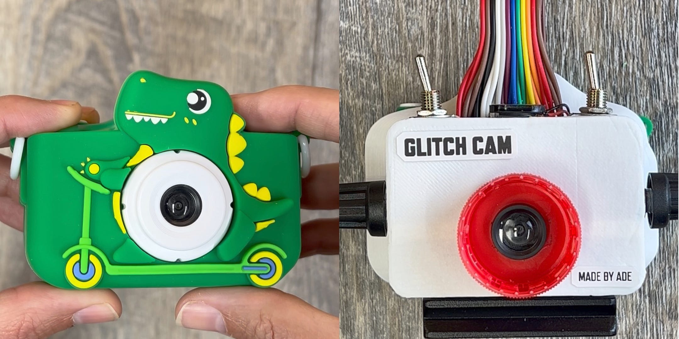
This is the story of a glitch camera I made out of a toy camera. It started out as a dinosaur on a scooter and ended up as a glitch making machine. Here’s the before and after photo…
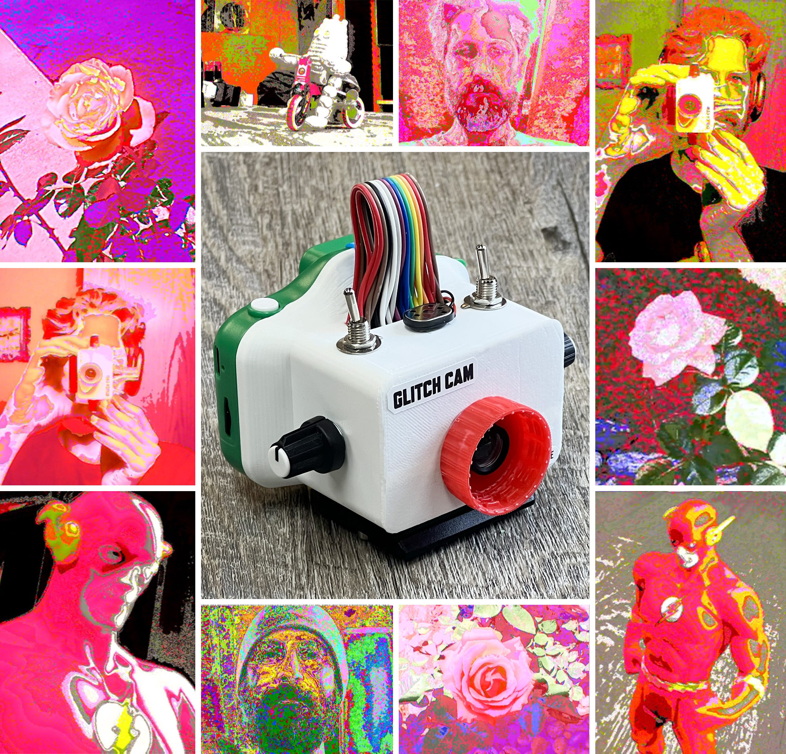
Ok, why would somebody make a glitch camera? Perfection is overrated. Who wants megapixels and expensive gear that barfs out realistic images that look like everyone else’s? Well, lots of people actually, but maybe not you. Are you the type of person who likes to make their own gear and strives for originality and artistic expression in the pictures you take? If that sounds like you then maybe this DIY project has your name on it. Below is an example of some of the glitch effects that a camera like this is capable of producing.
Before diving into the tutorial, here’s a disclaimer. This isn’t an electronics tutorial. I’m not going to explain soldering, circuits, or 3d printing. If that’s what you are looking for, here are a few links made by people who are better than me at the technical side of this hack:
Start with Mike Sisk’s video and see if you have the soldering ability necessary to do this hack right. He goes over the basics and does a better job of explaining how the actual circuit bends work.
If you aren’t great at soldering, here is a guide to a connector strategy from LBVP similar to what I did. You might also want to watch Get Circuit Bent’s video about his breakout board design.
For the files for 3d printing and a helpful starting point for what pins to play with, here is a helpful github repo.
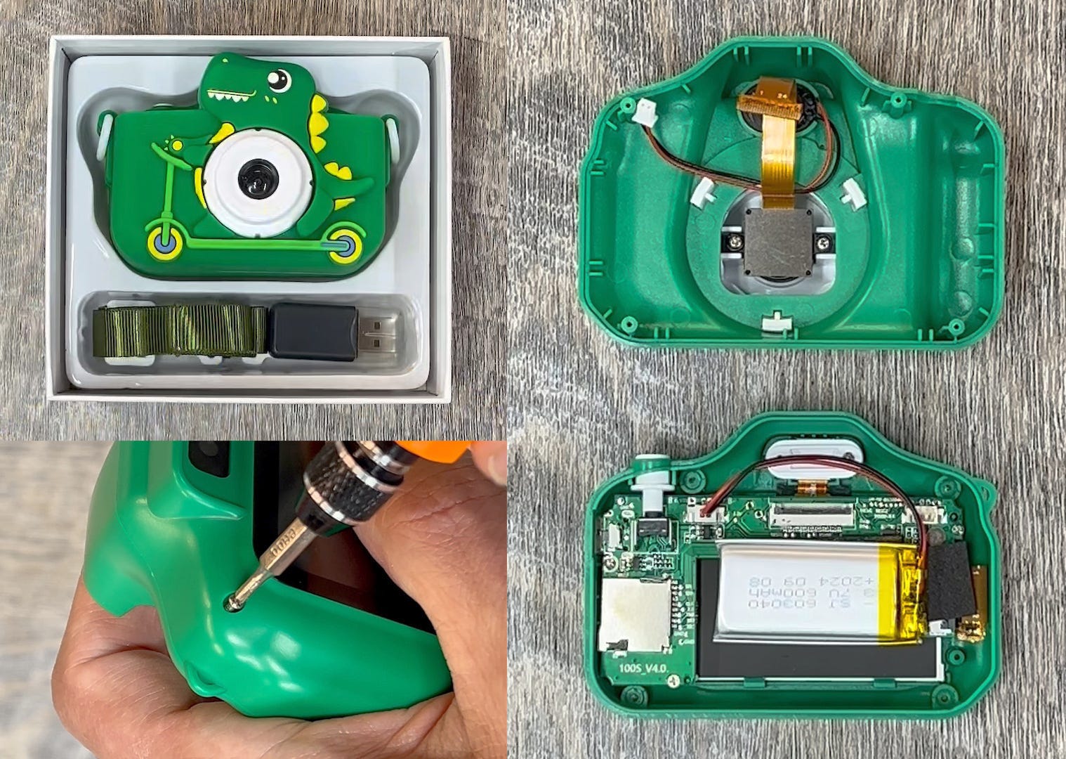
Let’s go! The camera I used is a dinosaur-themed Mgaolo Kids Camera. It was around $25 on Amazon and also comes in unicorn or puppy if you prefer. There are similar cameras like this available under different names. I read that some of them have different pin configurations so the pin numbers might be different so just a heads up. Also, I don’t think they all have a rear camera like this model.
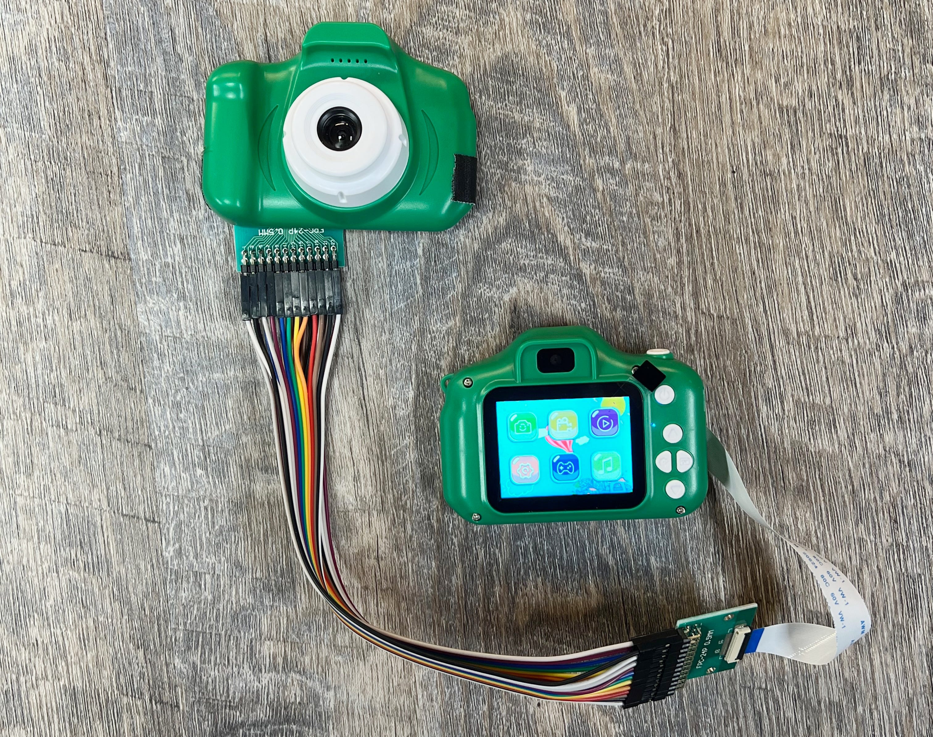
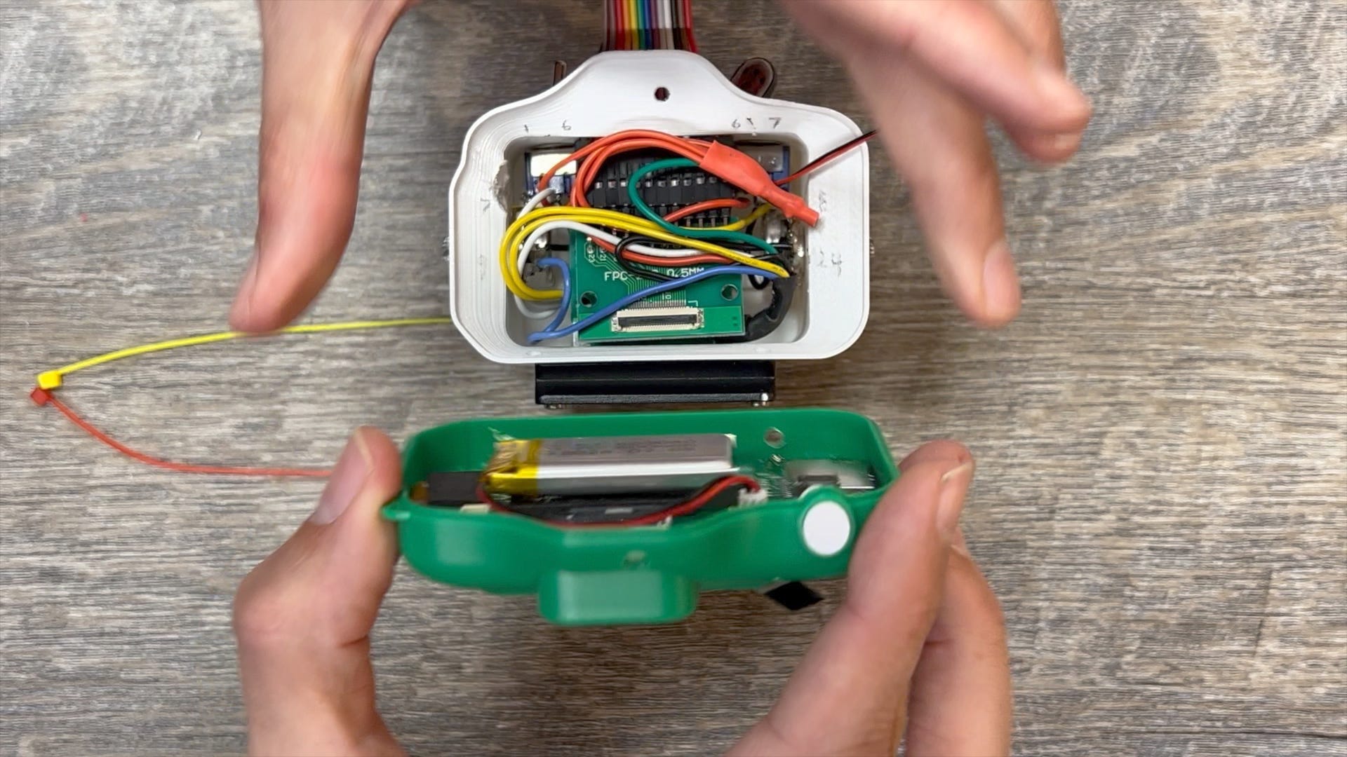
The basic idea is simple. You open the camera up and there will be a ribbon cable connecting the lens half to the back half. We are going to put wires and knobs in between. This is the art of circuit bending in a nutshell. Or in our case it is in a dinosaur shell. Dad jokes aside, here is what the guts of the dino camera look like.
If you are a pro, you could make all your connections directly on the board at the point where the ribbon cable connects. The challenge is that this connector is very tiny and unless you have a microscope and great soldering skills you are going to struggle to connect the pins. The advantage, however, is that this would keep things small and you can use the original camera case to enclose the entire hack in the original camera case. I am not that good yet, so…
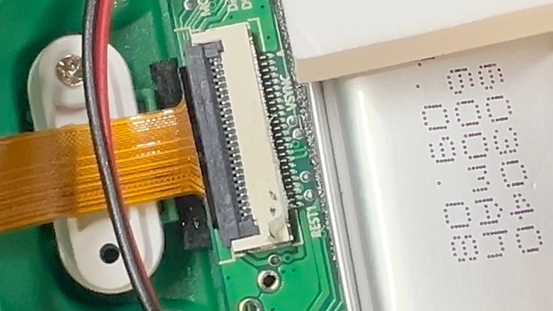
I opted for breaking the cables out with a connector. It cost half as much as the camera, but that’s the price you pay for sucking at soldering. The important numbers to look for when buying a connector are the “24 pins” and the “0.5mm” pin width.

I used colored wires to connect the pins. No soldering is necessary to connect all 24 pins as long as you get the wires with female connections on both sides. They look like this:

The only other part you need to buy (assuming you have a soldering iron, wire cutters, etc.) is a 24 pin 0.5mm ribbon cable to go from the connector back to the camera. With all that setup it looks like the picture below. Even before any hacking, this is a good time to plug it all in and make sure it still works. If you get a color bar screen, or the camera keeps rebooting it probably means the cables aren’t connected in the right order. Trace the connections and make sure the same pins that are coming out of the lens are going into the same spot on the camera board. All we’ve really done is extended the wires from the lens to the camera. But now we have big targets for experimenting and testing the glitches we want to generate.
Now the fun begins. There are 24 pins/wires to play with. When you touch wires together the signals mix, causing glitches. Not all wires glitch. And some will crash the camera. Assuming you don’t fry the camera, if the camera freezes or reboots you have learned a combination of wires to avoid.
When you find a cool effect, note the pin numbers. Again, camera models may vary but the pins that gave me the best results were combinations of 1, 6, 7, 8, 9, and 24. Documentation seems spotty so be prepared for trial and error. This github repo might help.
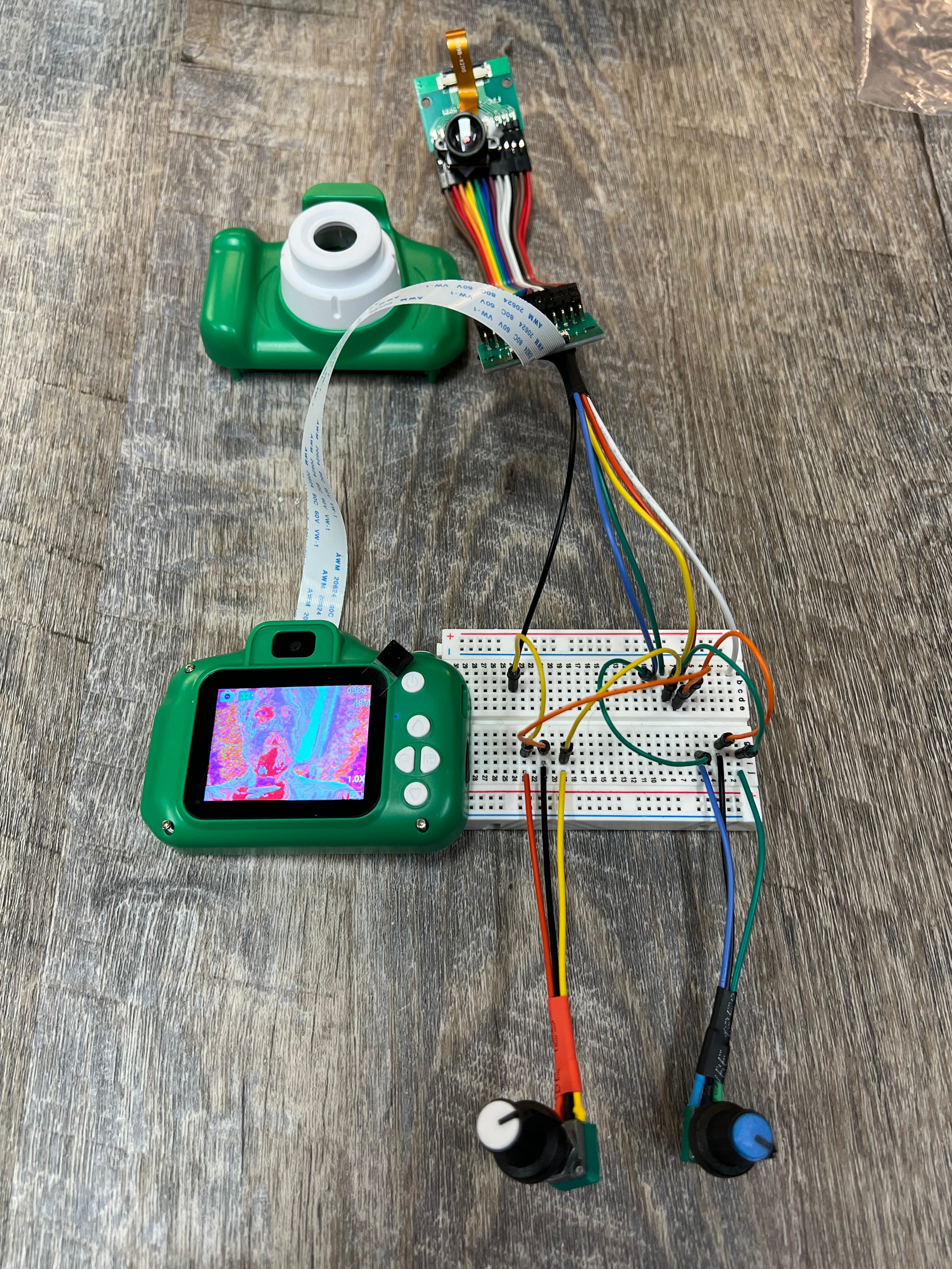
Here is what my setup looked like at this stage of the process. I pull wires from the connector and onto a breadboard where I can figure out how I want my potentiometers and switches to work.
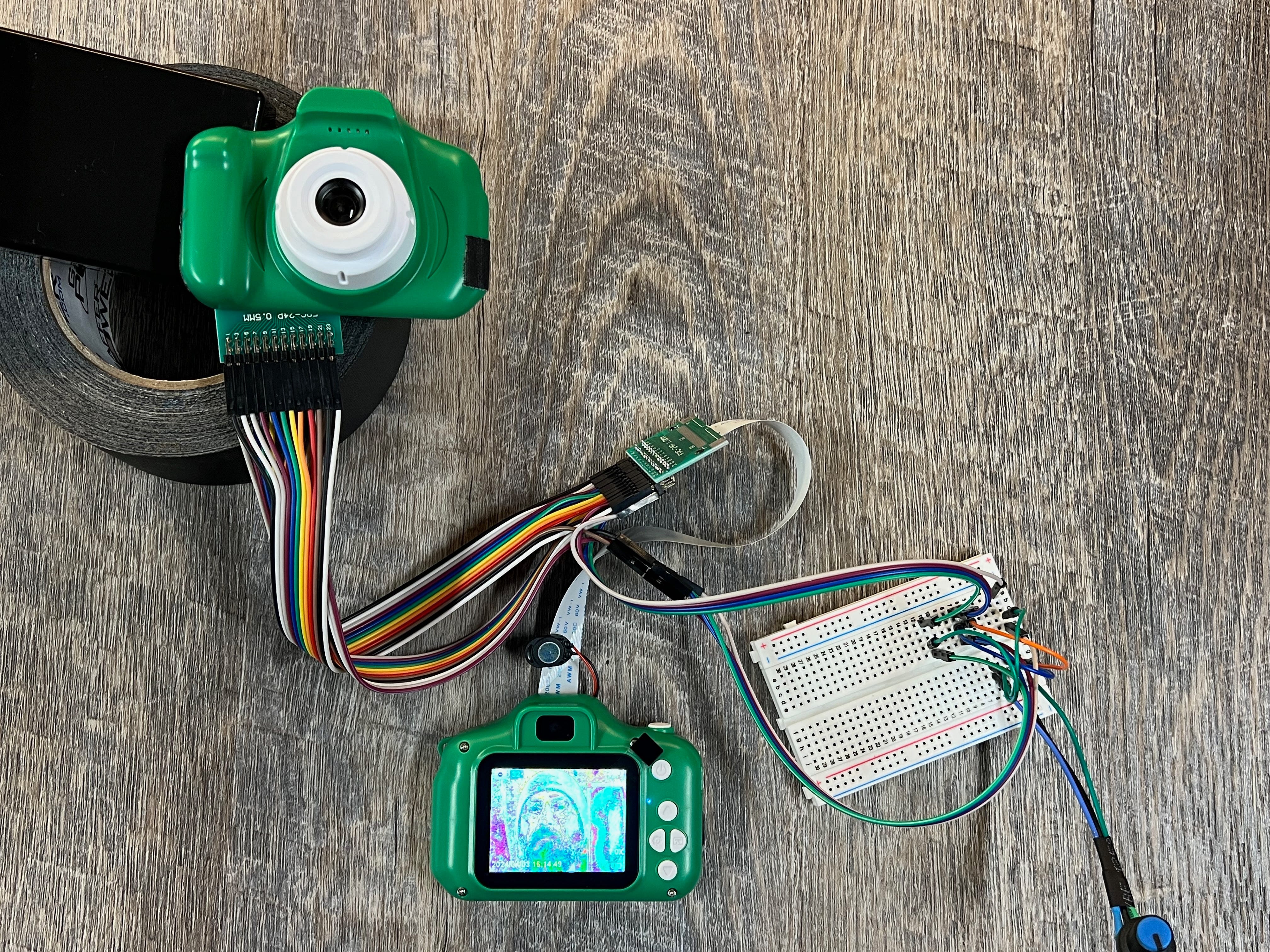
Explaining the potentiometers and switches is a bit beyond the scope of this tutorial. If you are new to electronics this might be a frustrating step, but the effort to understand basic circuits will be worth the mental investment. So stick with it.
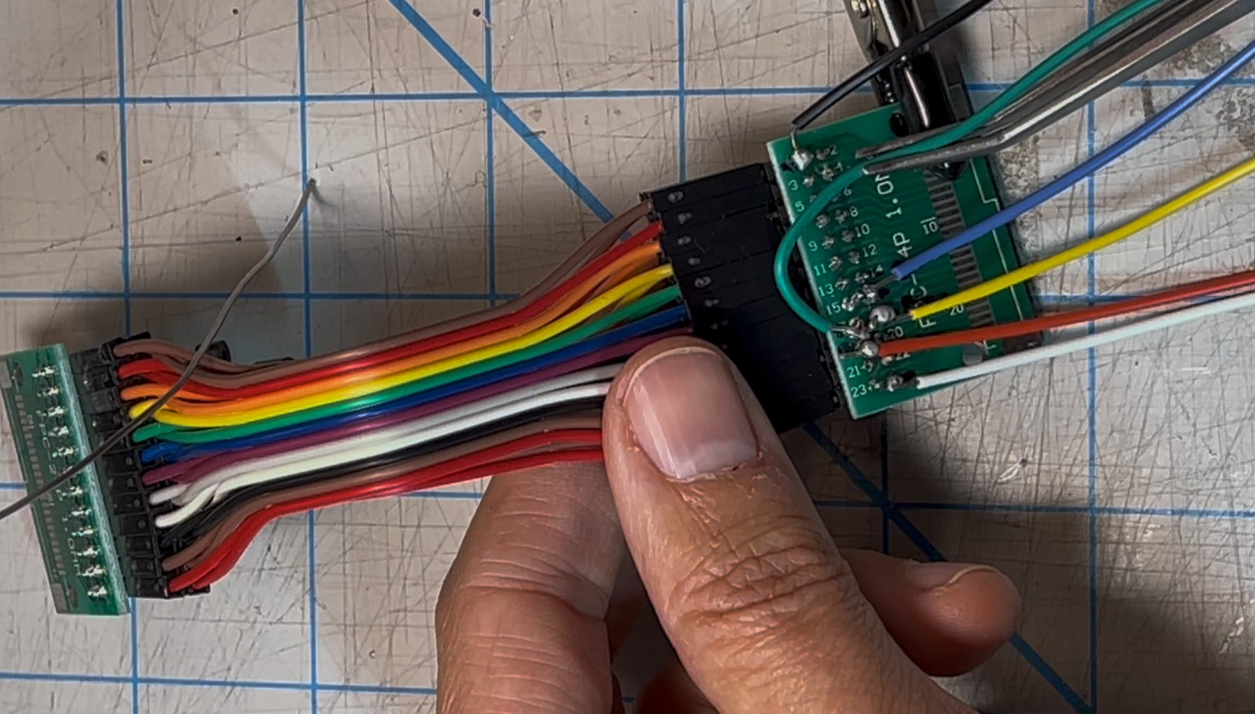
Through trial-and-error I identified the pins I would be using. Then I soldered them to the connector. Don’t judge, but I’ll show you my soldering just to prove that someone as bad as me can do this hack. In the photo below you can see how I connected into pins 1, 6, 7, 8, 9 and 24.
That’s enough of the electronics part. Once everything is working the way you want them to, it’s time to put everything back together. How are you going to fit that mess inside the camera? This is where you can personalize how you want your camera to look. The sky is the limit, but I opted for a 3d printed case. I got the 3d design from LBVP and the only change I made was to make it a bit shorter.
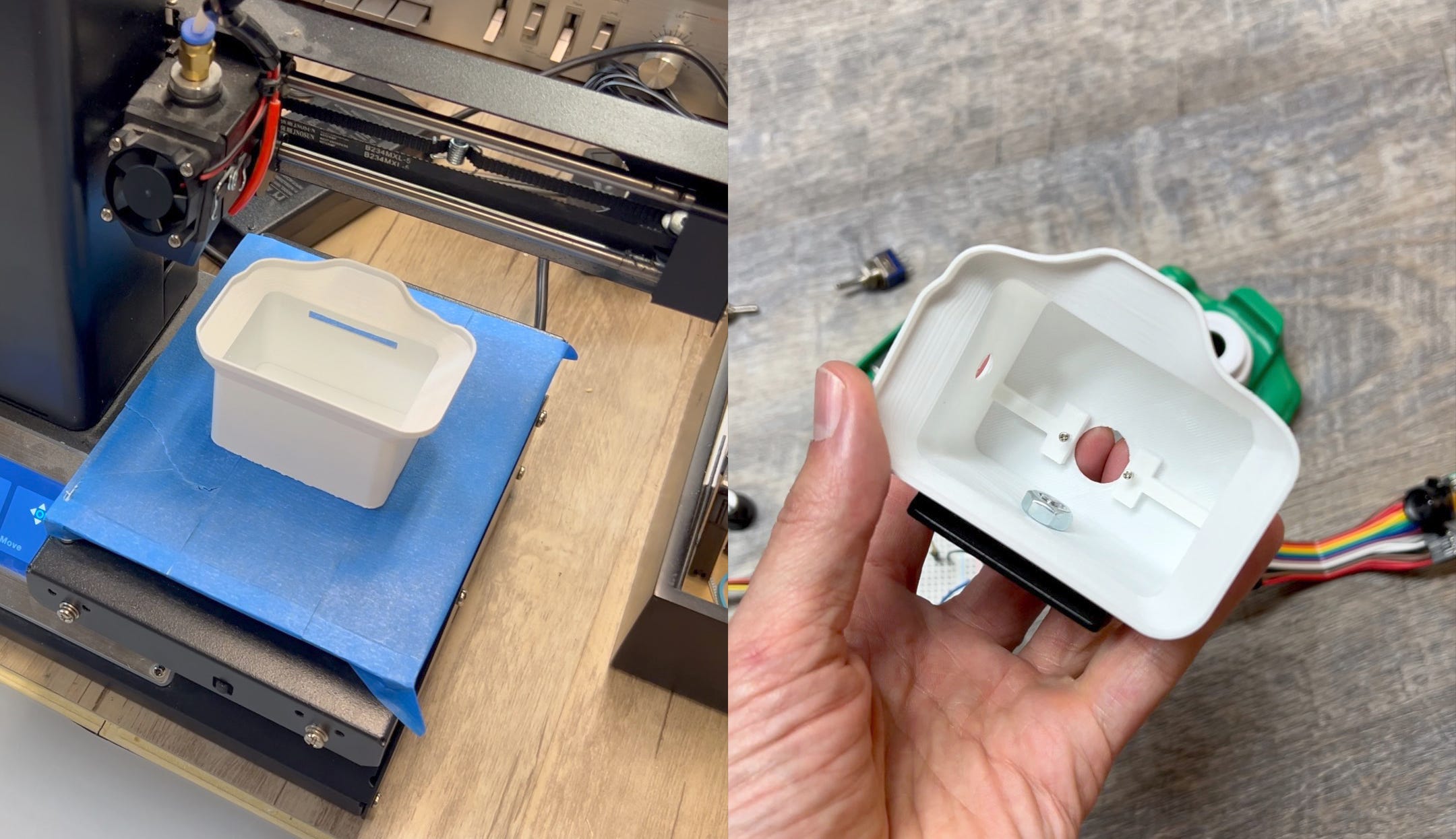
I drilled holes for my 2 switches, the 2 potentiometers, and a tripod mount. You can see below that I noted the numbers of the pins with a pencil on the white plastic to help me keep track of what pins go where. I wanted the switches on the top and the knobs on the right and left.
After confirming that everything was working I used zip ties to hold the case together.
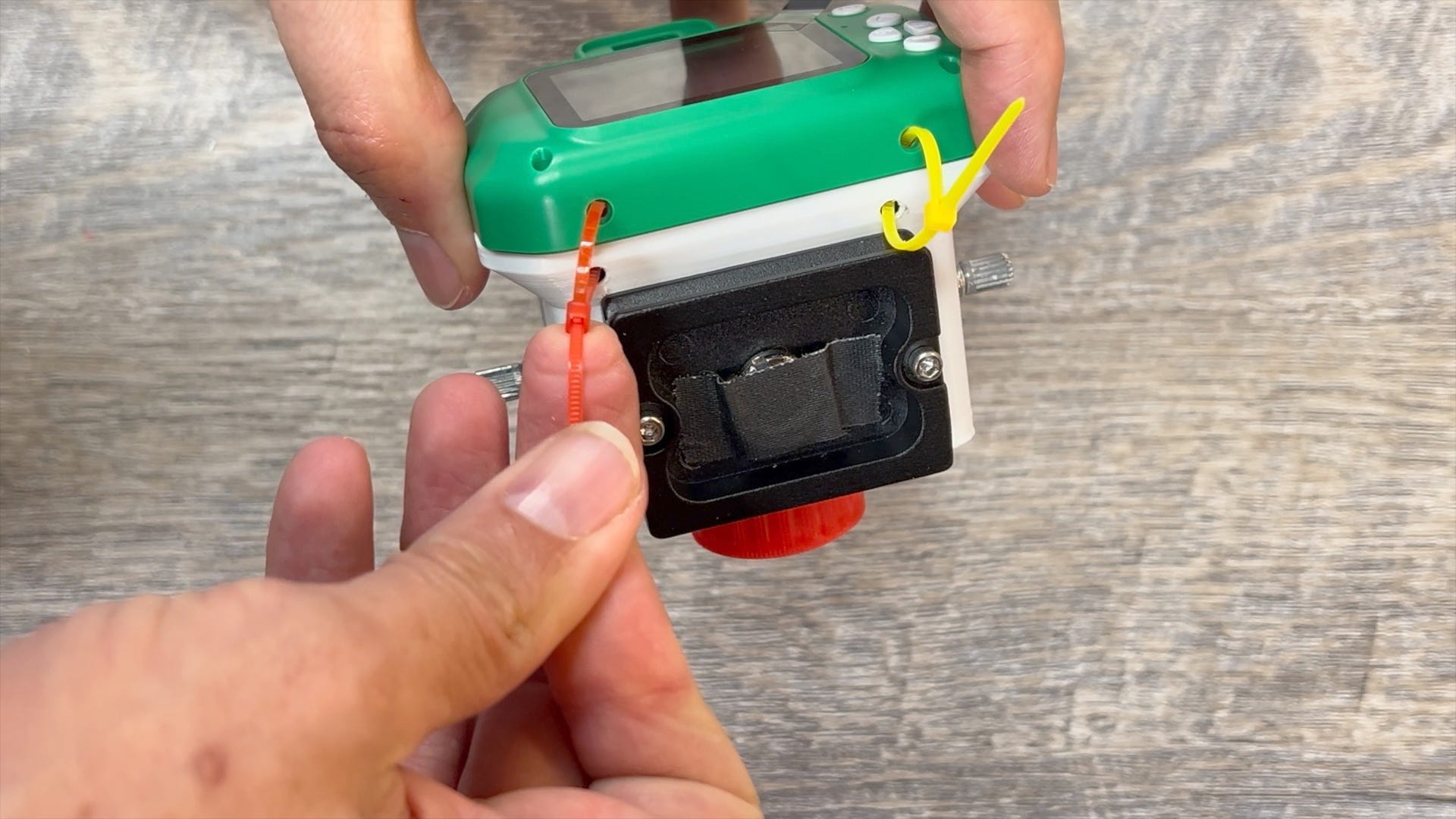
A quick note on the camera’s microphone. Since I am not re-using the front side of the camera, the microphone was disconnected and re-attached to my 3d printed case. You can see it in the photo below between the two switches.
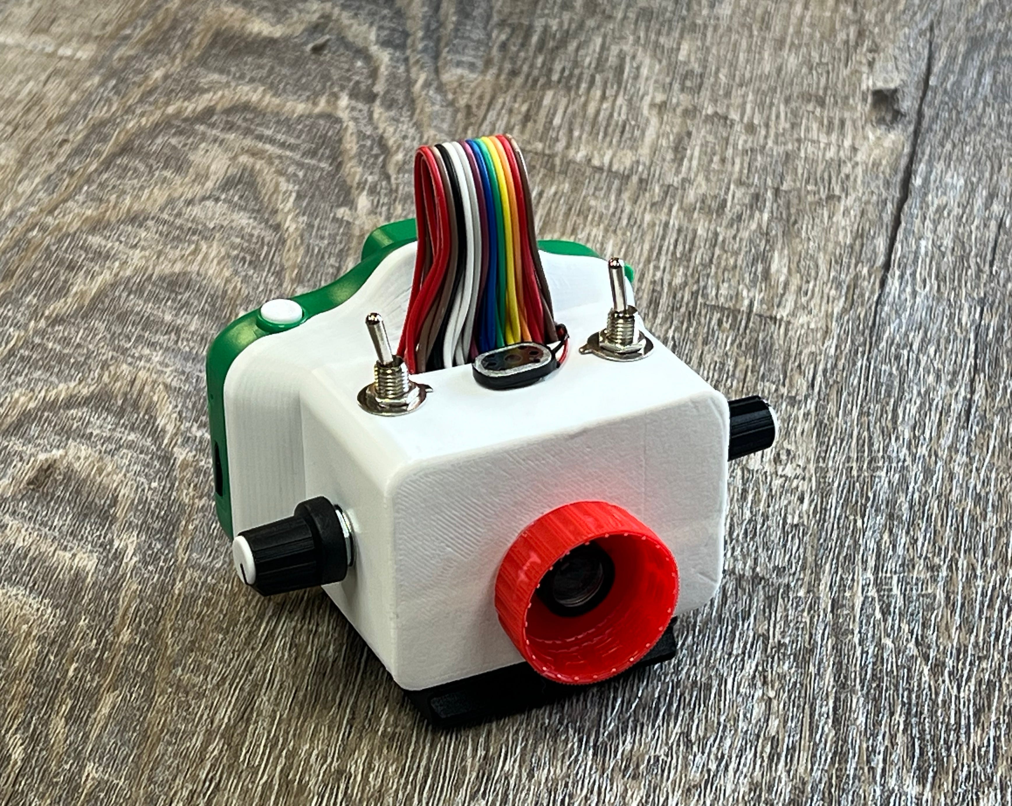
The finishing touches were to add a coke bottle cap to the front for extra rizz and some stickers for “branding.” It’s kind of cute, isn’t it?
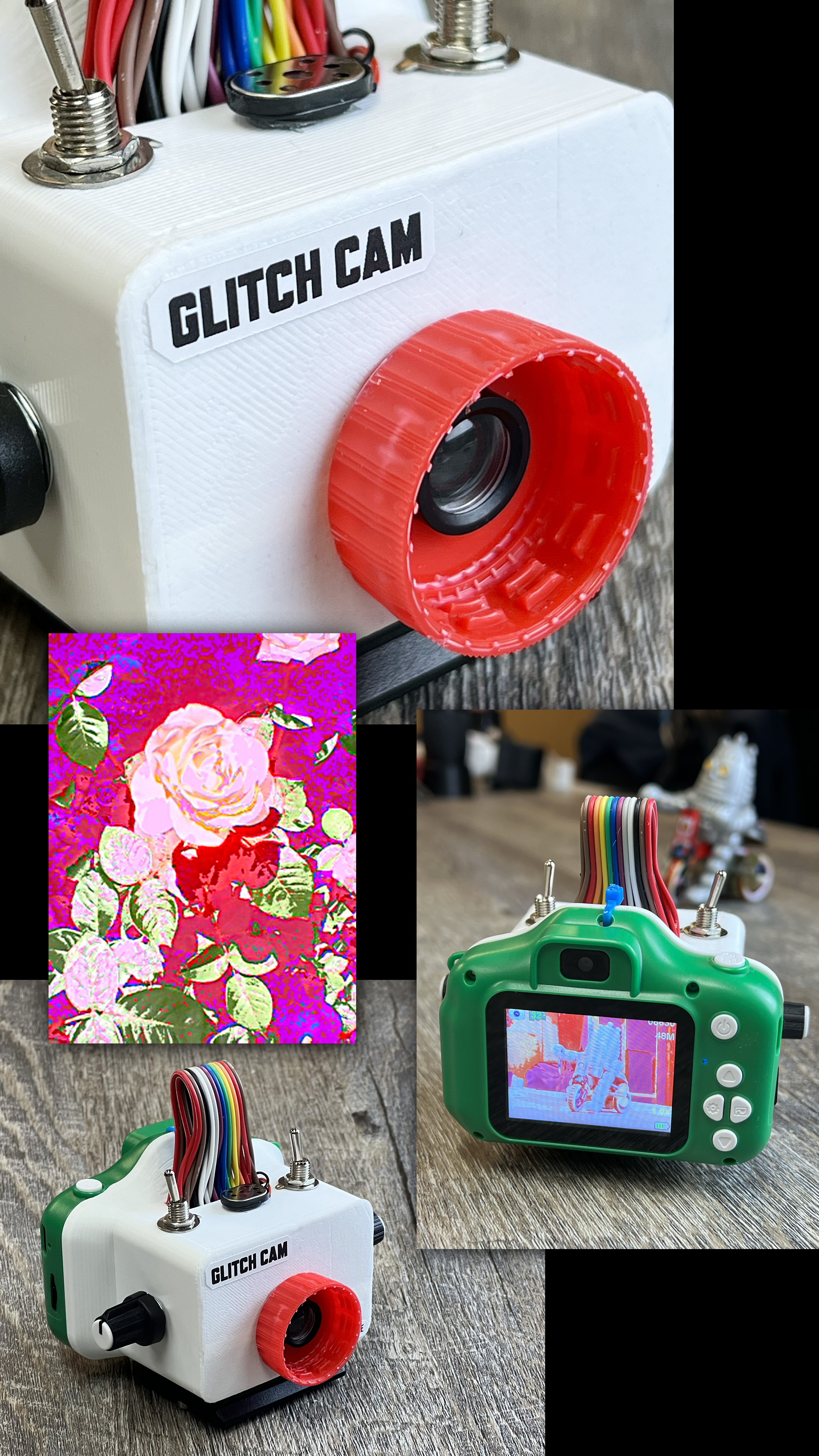
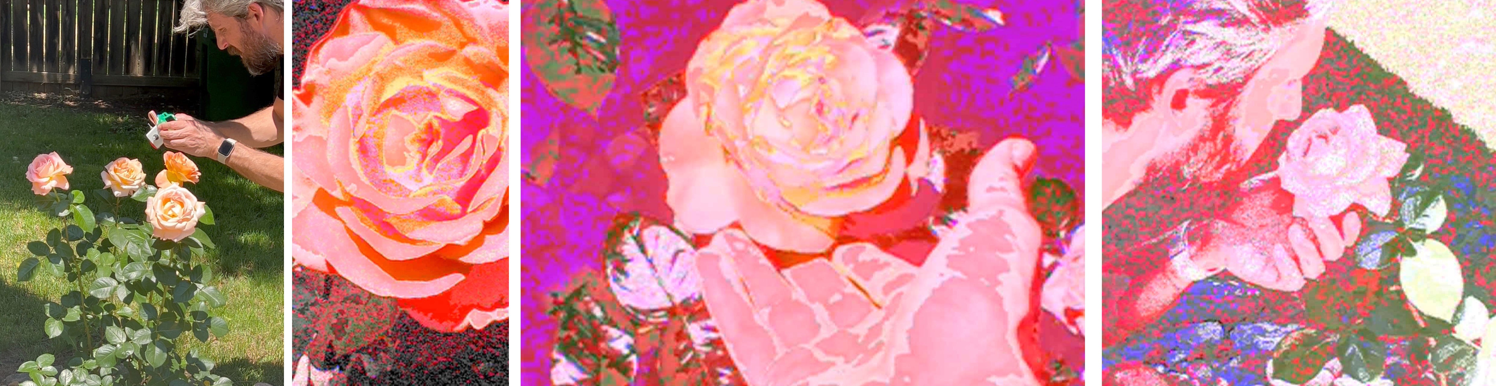
With the camera complete, it’s time to get outside and smell the roses. Here’s me using the glitch camera along with samples of what the camera is capable of producing. Did I forget to mention that it takes video, too?
I hope you enjoyed my story about making a glitch camera. If you made it to the end, you should probably subscribe to this Substack and follow my Instagram account (@ade3) where I document my wacky experiments. And if you know somebody who would enjoy this project, would you forward it to them?
Stay creative.
Your friend,
Ade
Awesome stuff, I may give this a try after I brush up on my soldering skills. I’m into weird stuff with photography. I’m happy I found your site
Awesome write up, thanks a lot for going into your process! For anyone else following along to this post don't be a dummy like me and not fully comb through the linked resources. Make sure the ribbon cable you get is a "type b" ribbon cable, otherwise the camera screen is going to show those color bars because the connections are reversed.